LightStanza offers a robust way of modeling electric lighting from concept to construction drawings. LightStanza is flexible so there are several workflows design and engineering teams can use. Some teams will prefer to place fixtures in Revit, while others want to augment Revit, SketchUp, and Rhino drawings with fixtures. Drawings that start in Revit format are best supported right now.
LightStanza allows users to layout and calc fixtures in a space, building, or exterior in a variety of ways:
All workflows for fixture layouts in LightStanza have in common:
LightStanza is a full-featured electric lighting design and analysis program.
The figure below describes a typical workflow of assigning luminaires to run calculations.
1. Set your calculation mode to electric light only. This should be the default for models that were imported from Revit with electric lighting checked.
2. Go to wireframe mode to see all of your photometric webs and IES files.
3. Assign IES files to your fixtures. The fixtures without IES files can be identified in the 3D viewer by a red warning indicator, and yield symbols in the luminaire manager. Not all fixtures have to be assigned to run calculations.
Once assigned, click the name of an IES file to edit in LightStanza’s advanced IES/Family Manager. Here you can view IES file details, BUG ratings, and photometrics, as well as change LLF (light-loss factors), fixture dimensions, and more (see Luminaire Manager).
4. Create new fixtures online and place them in your model.
5. Mark all fixtures that will contribute to Emergency Lighting mode (and set their dimming/power level).
6. Enter the instance manager to edit individual fixture properties. Here you can change rotations, height adjustments, set individual fixtures to emergency lighting, etc.
7. Run calculations in standard mode
8. Run calculations in Emergency Lighting Mode
Navigate to the Illuminance Grids panel on the left-hand panel. Select the “crop” symbol under the area of interest to crop the model to that space. Uncheck the “crop” icon to return to the whole building model.
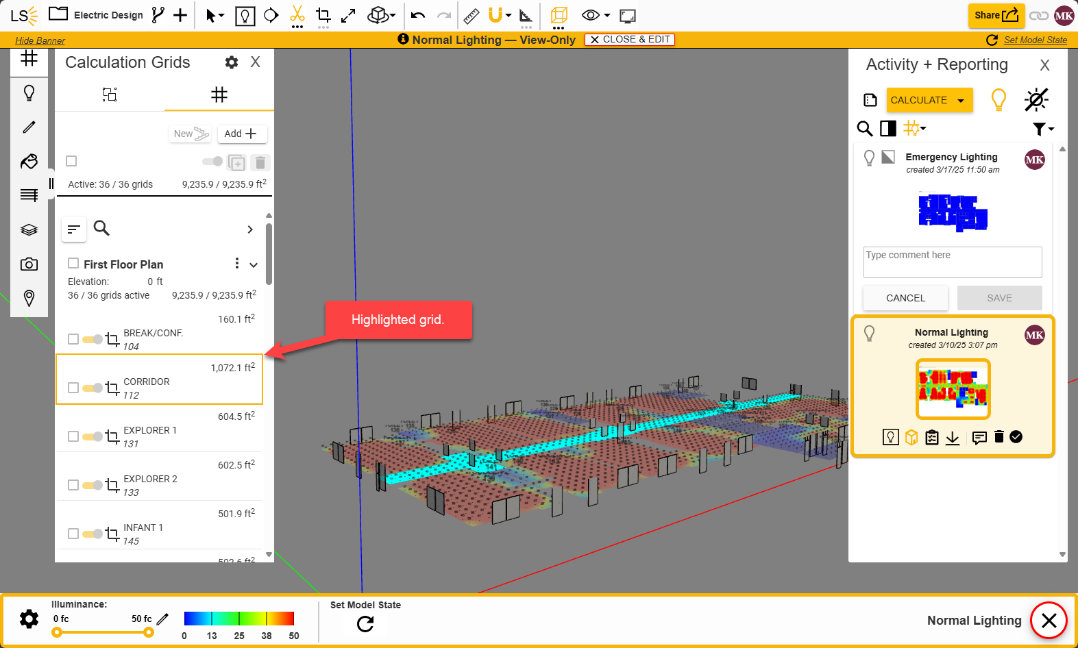
The Activity Bar (on the right side of your design screen) is where new activities are started, previous activities are referenced, model edits are listed and comparison reports are kicked off.
6. Navigating Activity Panel Tools – The top of the Activity panel holds several buttons to compare, view, and edit your model.
7. Viewing Previous Activities – Each card in the activity bar is an individual activity. The cards consist of a few basic navigational elements.
This panel allows users to create and add fixtures, assign and adjust IES files, and set up Emergency Lighting in their model.
Each fixture type in LightStanza can be addressed through this panel.
Fixtures can be created in LightStanza in various ways:
1. Importing lighting families from a Revit model
2. Creating a new lighting family (without fixture geometry) to hold an IES file – ideal for those that wish to design in LightStanza, regardless of where the model geometry is imported from
3. Adding a fixture that was previously saved into the family library
4. Adding more instances/copies of a fixture already present in the design (via one of the above methods)
You can create, delete, and move fixtures in LightStanza. The following figure illustrates these steps:
1. Navigate to a 2D lighting plan view (recommended – you can edit and create luminaires in any view mode). Use this dropdown menu to navigate between model levels.
2. Click on the fixture you want to move. Right click lets you perform many other operations as well such as, Delete, Copy, Mirror, Duplicate, Replace, Array, Rotate, Align (horizontally or vertically), and Aim.
3. Use your keyboard to move the fixture. See keyboard shortcuts above.
4. You can also add and remove fixtures using the top menu and batch selection.
Use an adjustable grid to assist placing light fixtures in the model:
You can directly upload an .ies file into LightStanza or choose one from your team’s online library. Upload and assign fresh .ies files, or store them in your LightStanza library for easy assignment and management.
Each fixture instance in LightStanza can be individually addressed through this panel.
Method 1: Single IES File
This method assumes you have a single IES file that contains both the direct and indirect intensity distributions. Many manufacturers can provide this type of file, or it can be created manually by combining the direct and indirect files outside of LightStanza.
Method 2: Multiple IES files.
This method assumes you have 2 IES files from the manufacturer. One for the direct component and a second for the indirect component. Basically, you want to create to luminaire types. One to hold the direct and another to hold the indirect file.
This panel allows you to customize your IES file and make adjustments to light source position/orientation within the family.
Features Include:
1. Horizontal illuminance grids will be generated in the LightStanza model per Rooms or Spaces assigned in Revit.
2. Create vertical illuminance grids on the walls of each room or space.
A horizontal illuminance grid will be created in the LightStanza app. You can adjust the height of this using the editing tool in the Illuminance Grids Panel.
3. Adjust the “Room Type” assigned to the grid by clicking on the light bulb.
4. A “Room Type” for that illuminance grid will be assigned based on the room or space type defined in Revit. An illuminance target and whether that target is an average, max or min will be defined based on that room or space type. These conditions are editable for each illuminance grid imported from Revit.
Vertical illuminance grids have been created on each wall within the imported Revit model. Toggle the vertical illuminance grids on and off to customize your design.
You can tag your peers in your designs and result reports.
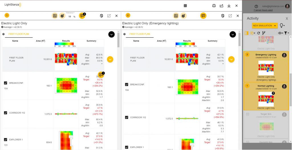
Users have the ability to download their report from the activity panel.
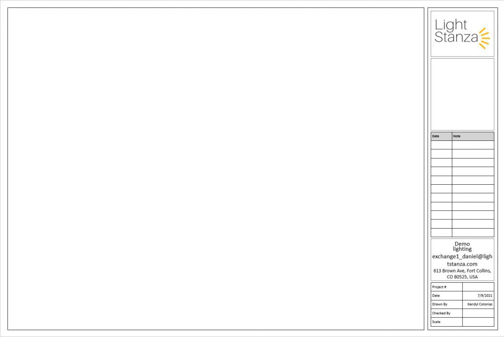
Once downloaded the user can click on the ppt. file labeled ‘report sheet template’ to start creating sheets.
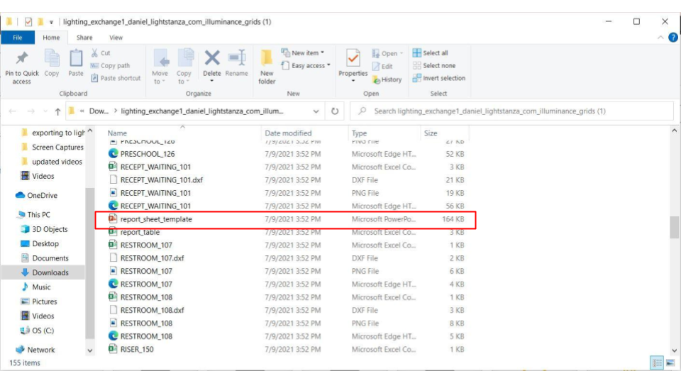
The template is completely editable. From here you can copy and paste an image of the calcs and the calc summary or what ever information is required to present on your sheets.
The most developed electric light modeling workflow is with the LightStanza Revit Plugin, which can be found on our Plugins Page.
LightStanza’s Revit Plugin allows design teams to quickly export relevant geometry, fixtures (optional) and IES files from a Revit document to LightStanza. Users can try out different concepts, run calculations, bring results back into Revit and other reporting programs.
Geometry | Revit → LightStanza (Export) | Revit→ LightStanza (Send Changes) | LightStanza → Revit |
Revit/Model Geometry | ✔ | ✔ | |
View Template Filtering | ✔ | ✔ |
Tilt Fixture✔✔
Fixture Action | Revit → LightStanza (Export) | Revit→ LightStanza (Send Changes) | LightStanza → Revit |
Add Fixture | ✔ | ✔ | ✔ |
Copy Fixture | ✔ | ✔ | ✔ |
Delete Fixture | ✔ | ✔ | ✔ |
Move Fixture | ✔ | ✔ | ✔ |
New Fixture Family | ✔ | ✔ | GLF |
New Fixture Family Type | ✔ | ✔ | ✔ |
Replace Fixture | ✔ | ✔ | ✔ |
Rotate Fixture 2D Plane | ✔ | ✔ | ✔ |
Light Fixture Family Host | Revit → LightStanza (Export) | Revit→ LightStanza (Send Changes) | LightStanza → Revit |
Ceiling Based | ✔ | ✔ | GLF |
Face Based (On Vertical Face) | ✔ ✔ | ✔ ✔ | ✔ VF |
Floor Based | ✔ | ✔ | GLF |
Non Work Plane-Based | ✔ | ✔ | ✔ |
Roof Based | ✔ | ✔ | GLF |
Wall Based | ✔ | ✔ | GLF |
Work Plane-Based | ✔ | ✔ | ✔ |
Revit Parameters | Revit → LightStanza (Export) | Revit→ LightStanza (Send Changes) | LightStanza → Revit |
Active (LightStanza) | ✔ | ✔ | ✔ |
Color | ✔ | ✔ | |
Color Filter | ✔ | ✔ | |
Custom Parameters | |||
Emergency (LightStanza) | ✔ | ✔ | ✔ |
Emergency Output (LightStanza) | ✔ | ✔ | ✔ |
Emit Circle Diameter | ES | ES | |
Emit Line Length | ES | ES | |
Emit Rectangle Length | ES | ES | |
Emit Rectangle Width | ES | ES | |
Family Name | ✔ | ✔ | ✔ |
IES Basis Length | ✔ | ✔ | |
IES File | ✔ | ✔ | ✔ |
Initial Intensity | ✔ | ✔ | |
Light Loss Factor | ✔ | ✔ | |
Luminous Length (LightStanza) | ✔ | ✔ | |
Tilt Angle | |||
Type Mark | ✔ | ✔ | ✔ |
Type Name | ✔ | ✔ | ✔ |
ES: Emit from Shape Parameters are dependent on which Emit Shape is selected from the Light Source Definition in the Light Fixture Family.
GLF: Generic Light Fixture – If a light fixture family is sent from LightStanza → Revit with one of the noted Host types then the fixture will be placed as a generic light fixture.
VF: Vertical-Face – Light fixtures that are placed on a vertical surface (wall) in Revit and position is changed in LightStanza will still be attached to the vertical surface in Revit when changes are synced. Also adding/copying a fixture in LightStanza that is on a vertical face will place the fixture horizontally in Revit when changes are synced. For best results with vertically placed fixtures edit/add the fixture in Revit and sync changes to LightStanza.
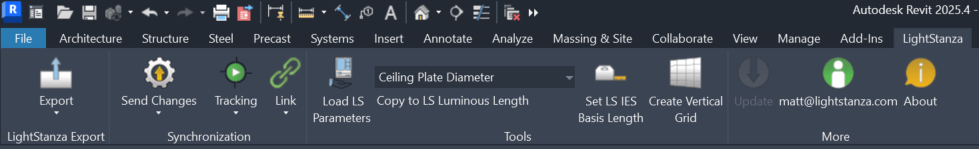
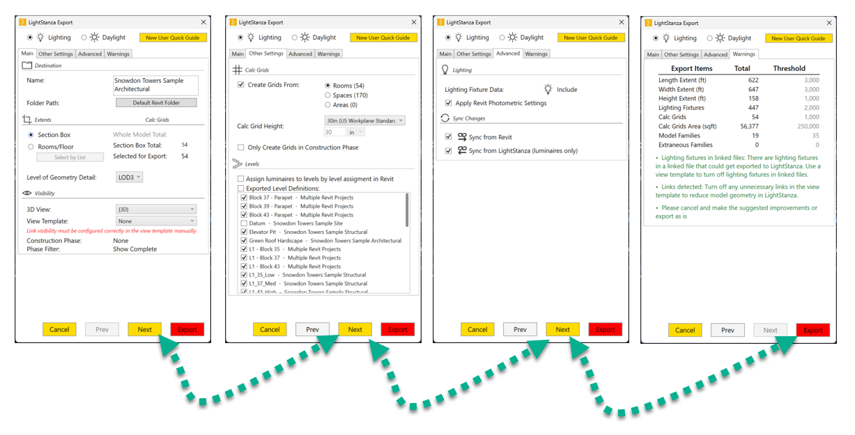
Once you install the LightStanza Plugin, open up Revit and under the LightStanza tab log into your LightStanza account. Then go to the “Export Button” and click “Export”.
The plugin must have a 3D view in Revit to export to LightStanza. What you see in the 3D view is what will get exported to LightStanza.
A view template can be applied to the 3D view to trim out model elements that aren’t needed for analysis (e.g. fire alarms, conduit, pipes, railings, plumbing, etc). These items will greatly increase the data exported to LightStanza and aren’t needed for calculations in most cases.
Applying a section box to the 3D view will trim out anything outside of the section box. This is useful to ensure only the part of the model you need for analysis is included, and not outlying elements (e.g. site/terrain geometry).
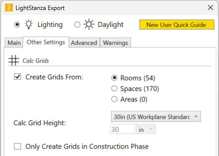
Calculation Grids are automatically created from the rooms or spaces defined in the Revit model during the export process. You can also create grids in LightStanza.
Export Option | Description |
---|---|
Name | The name of your LightStanza Design. |
Folder Path | The folder you want to export your design into. |
Extents | Allows you to crop your model to a particular level, room or space before uploading to LightStanza. This can dramatically improve export and simulation times. |
3D View | The view that will be used for the export process to LightStanza. Anything not visible in this view will not export to LightStanza. |
View Template | The view template that will be used for the export process to LightStanza. The view template will be applied to the selected 3D View and will only export Revit Categories that are selected in the view template to LightStanza. |
Create Grids From | Create calculation grids in LightStanza based on either Rooms or Spaces. Applies to linked files as well. |
Calc Grid Height | The default height to use for calculation grids created from Rooms/Spaces. |
Only Create Grids in Construction Phase | If checked, calculation grids will be added for Rooms/Spaces/Areas in the New Construction phase only. |
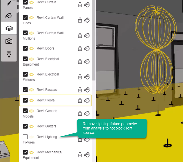
Lighting Fixture Data | Lighting fixtures and lighting family data will/will not be included in the exported model. |
Sync changes | Track changes from Revit to LightStanza (can be toggled later). |
Apply Revit Photometric Settings | Will use the lighting type parameters set in the Lighting Fixture Family for Light Loss Factor, Initial Intensity, Color, Color Filter, and light source dimensions. Without this selected, all data will be set based on IES file parameters (if present). |
Sync changes from LS to Revit | Track (lighting fixture) changes for syncing from LightStanza back to Revit. |
Step 4c. Review Warnings. Before exporting, check the warnings tab to ensure all parameters are within tolerances. LightStanza will perform best if all totals are below the threshold quantities. If any parameters exceed the tolerance values, the export can still succeed but calculation performance may be degraded.
Warning type | Description |
---|---|
Extents | The linear extents to be exported in X, Y, and Z directions. |
Lighting Fixtures | The total number of Lighting Fixtures to be exported. |
Calc Grids | The total number of calculation grids to be exported. |
Calc Grids Area | The total surface area of all calculation grids to be analyzed. |
Model Families | The number of family categories to be exported to LightStanza. |
Extraneous Families | Certain categories with high levels of geometric detail that should typically be excluded from the export. |
Parameter | Description |
---|---|
LS-Luminous Length | The length of the linear fixture |
LS-IES Basis Length | The length of the IES file |
LS-Active | Include/Exclude from regular (non-em) simulations |
LS-Emergency | Fixture should be an emergency fixture |
LS-Emergency Output | Output of the fixture during emergency calculations |
In order to access LightStanza Revit Parameters click “Load LS Parameters” in the ribbon for the LightStanza plugin in Revit. This will automatically add parameters to each individual lighting fixture.
Assign the “LS-Luminous Length” as the intended length of that light fixture type.
Navigate to the Type Properties of each light fixture type and under Photometrics, assign “LS-IES Basis Length” as the length of the luminous box of the base IES file that will be used in the calculations.
To assign a fixture as emergency prior to interfacing with the LightStanza model, use “LS-Emergency” to designate each fixture you wish to mark as emergency. Adjust the emergency output of the fixture using “LS-Emergency Output”.
Marking fixtures as emergency prior to uploading a model to LightStanza will automatically designate those fixtures as emergency in the LightStanza model. These emergency fixtures will be included in Emergency Lighting Calculations.
If you are syncing changes to/from/between Revit and LightStanza, the emergency parameters can be edited from either location and kept in sync in the two applications.
Fixtures can be included/excluded from regular (non-emergency) simulations in LightStanza using the “Active” parameter. You can set the initial state of each fixture by toggling the LS-Active parameter on each instance before exporting.
After the initial export, you can use syncing to/from/between Revit and LightStanza to toggle this parameter in either place and have it kept in sync in the two applications.
In LightStanza, you will see the “Proration Factor: #.##” for each individual fixture instance. For example, this fixture is 16ft in length with a base IES file of 4ft. The IES file of this fixture has be prorated by a factor of 4.00 to create a 16ft luminous box.
On the activity card for the calculation information you wish to send back to Revit, click the icon to create a report.
Once in the report file, navigate to the icon highlighted in red in the image below. Clicking this icon will export scheduled information back to the Revit model. Syncing between LightStanza and Revit must be activated for this to occur.
In Revit, navigate to the “Schedules/Quantities” section of the Project Browser. You will see (2) schedules were created from the LightStanza model:
“LightStanza Luminaires” will provide a schedule of fixtures that were used in the model.
“LightStanza Report” will provide a full calculation matrix of illuminance values generated in the specified calculation.
See the “LightStanza Luminaires” schedule below:
See the “LightStanza Report” schedule below:
In addition to sending data from LightStanza as native Revit entities, it’s also possible to send report information as a DXF to overlay onto a floor or ceiling plan. Using this technique, you can import calculation results and luminaire symbols as a DXF, directly into your Revit project.
To do this, first ensure that the syncing from LightStanza is turned on by clicking the link button in the upper right-hand corner.
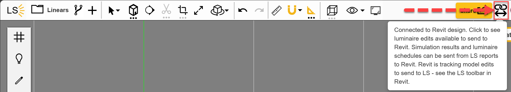
Next, in Revit, open the View in which you would like the DXF placed. Then, in LightStanza, open the report you would like to send to Revit. On either the total floor result image or a single grid result image click the “Send all DXF’s to Revit” or the “Send DXF to current Revit view” button. This will send the DXF(s) to Revit which will pop up a message telling you the DXF(s) successfully imported.
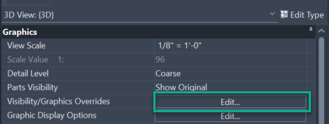
If you cannot see the DXF(s) please double check your Visibility/Graphics settings and make sure your Cut Plane is above your LightStanza grid height.
On the activity card for the images you wish to add to Revit, click the icon to create a report. Once in the report file, click on the “Download report data” button at the top-right. This will download a zip file containing all of the data in the report, including DXF format drawings of the results.
In your Revit design, navigate to the “Insert” tab and select “Import CAD”:
In the next dialog, navigate to the files downloaded from LightStanza, and select the desired image. Make sure to show files of type .dxf, and set the import units to meters. By default, Revit will load the image into the current active view, or you can select one in the “Place at:” drop-down:
Once loaded, you can align the image with the view by clicking and dragging if necessary.
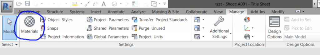
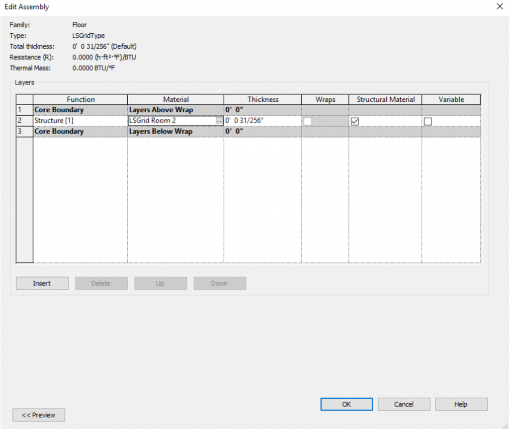
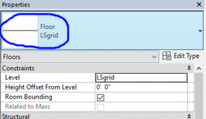
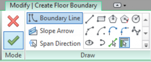
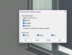
To resolve the issue of some glass panes exported to LightStanza coming in as solid objects you need to edit the Revit Family definition in Revit. The most important thing to check in the family file is that the visibility settings for the glass pane is set to the below picture. Go ahead an open the Revit Family File and select the glass pane that isn’t coming into LightStanza correctly. Then click on the setting “Visibility/Graphics Overrides” (in the properties panel). In the window that pops up the button “When cut in Plan/RCP” needs to be unchecked as this changes how Revit exports data to LightStanza.
When exporting linear lighting families to LightStanza from Revit where the linear distribution is symmetrical the photometric web will come in scaled correctly in LightStanza.
Whereas asymmetrical may come in pointed wrong or have the distribution parallel with the fixture instead of perpendicular. The root cause of this is because the manufacturer defined the IES file wrong. Generally, we recommend using a different fixture because it gets tricky to handle it. If you must use this IES file we can fix this through a series of workarounds for fixed length linear types but not adjustable length linears at the moment. In the Revit Family Definition we need to use a rectangle light source and flip the width/length. Then in LS we need to flip the width/length again in the IES file editor. After that the asymmetrical distribution will be perpendicular to the fixture length.
If Geometry is coming in weird to LS there are two things to check:
The LightStanza Revit plugin is capable of exporting native Revit elements, but not yet able to include geometry from imported formats such as a linked DWG files or 3D CAD files. However, it is possible to create a Revit family with imported CAD geometry. Note: Revit has both an option to “Link CAD” and “Import CAD”. Import is the best option for integration with LightStanza.
Once the family is created it can be added to the Revit project and exported to LightStanza as native Revit geometry. If the geometry does not appear correctly, there are some additional file conversion options to try.
The two parameters defined in Revit, LS-Luminous Length (instance parameter) and LS-IES Basis length (type parameter) are combined to determine the instance proration: proration = luminous length / basis length
At simulation time, a new copy of the base IES file is created with the luminous dimensions field adjusted to the correct length for each fixture instance. LightStanza does the work for you, instead of you having to create new IES files for each length or by lining up many short IES files into one long one.
The LightStanza simulation engine is built around Radiance, which adds IES files with specific dimensions to the model “scene” using the command ies2rad. Using the modified IES files for each fixture length (see point 2), this ensures that in both point calculations and renderings, the fixture outputs light along its entire length.
To account for spreading the total output of the IES file over a different length than in the original, the proration factor is also applied as a constant multiplier to all output values in the IES file.
LightStanza then runs the calculation using as many IES files as needed (one file for each different instance length), while you only need to manage one! This process will produce identical results as compared to e.g. chaining multiple non-prorated instances together to match the length of a single prorated one.
Checking and verifying proration factors.
There are several indicators in the LS interface to show/check that proration has been applied:
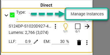
Luminaire Panel – Type View: the arrow button that opens the more detailed Luminaire Panel – Instances View will have a “P” underneath it, indicating that at least some instances of this type have a proration factor applied
Luminaire Panel – Instances View: The proration factor assigned to each instance is listed here, and can be edited if needed.
Model viewer: In the model viewer, the IES luminous dimensions are indicated by a transparent blue plane. You can verify that the luminous dimensions match the fixture geometry dimensions directly in the viewer.
Below you can see two instances of the same type, but with different lengths/proration factors. The light, solid-blue rectangle in the center of each fixture shows the luminous dimensions of the prorated IES file, which matches the length of the fixture geometry (the darker-blue rectangular outline):
4. IES/Family Viewer: In the IES/Family viewer you will see several notifications if any instances have a proration factor applied: